2001 Toyota Tundra 4.7 System Diagram

Add to Cart to.
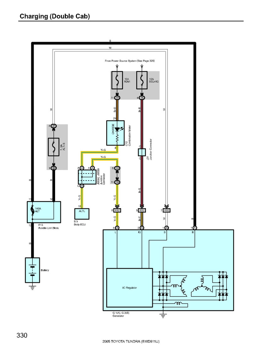
2001 toyota tundra 4.7 system diagram. Tundra P0440 Trouble Code Causes. UNDERSTANDING TOYOTA WIRING DIAGRAMS WORKSHEET 1 1. When troubleshooting a faulty ground point checking the system circuits which use a common ground may help you identify the problem ground quickly.
Describe and identify the diagram component U. Front AXLE Left Front AXLE RIGHT. TOYOTA 2001 TUNDRA 47L V8 Exhaust Emission Exhaust System Kit.
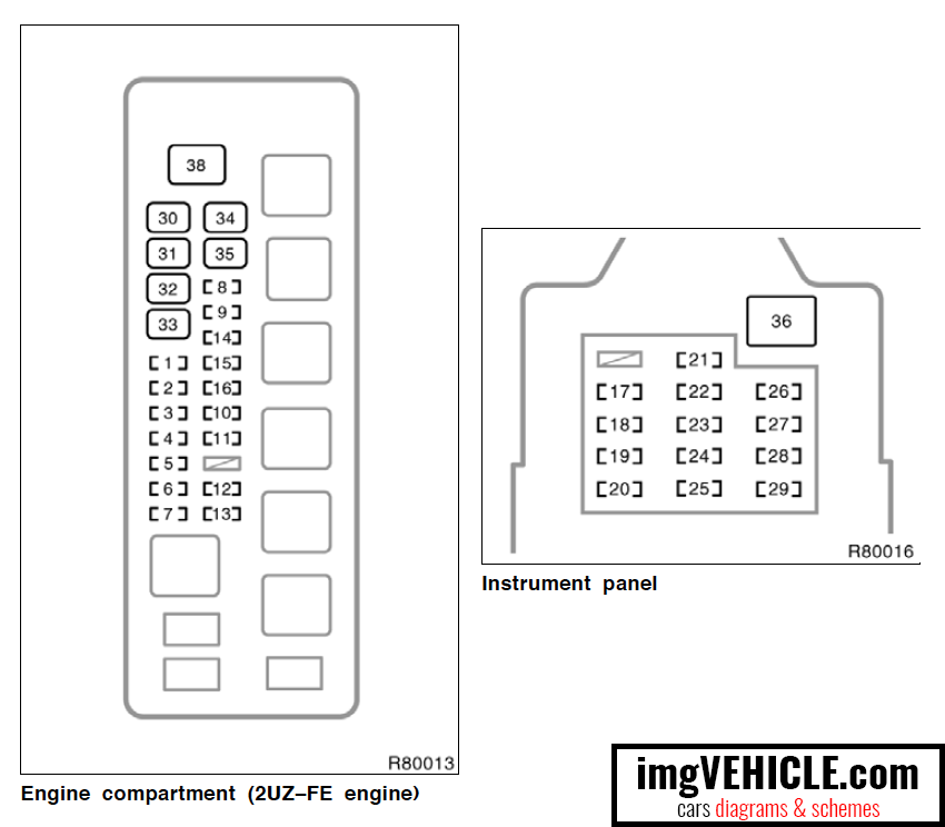
Engine compartment 2UZ- FE engine Toyota Tundra mk1 fuse box engine compartment 2UZ-FE Engine compartment 5VZ- FE engine Toyota Tundra mk1 fuse box engine compartment 5VZ-FE Engine compartment with towing kit. The standard type manual transaxle in which the driver operates the. 4 Wheel Drive Automatic hubs.
Describe the meaning of the C13 in the diagram component Q. Fuel tank components. Describe the meaning of the 2 in diagram component S.
I would like information on the supercharger for the 2001 Toyota Tundra with a V8 engine and 47 litre engine. Housing Assembly Bearing Camry. Toyota Tundra 2013 Fuse Box Diagram April 18th 2019 - Toyota Tundra 2013 Fuse Box Diagram Home Toyota Tundra 2013 Fuse Box 497 3 8 Other interior features 3 Interior and exterior features Fuel system 19 ETCS 10 A Multiport fuel injection system sequential multiport fuel injection system electric throttle control sys tem 20 MET B 5 A.
All Models Including Tundra Base Tundra SR5 Tundra Limited 2WD 4WD Standard Cab Access Cab Extended Stepside 34L V6 5VZ-FE 47L V8 2UZ-FE Engines. Describe the meaning of the G-W in diagram component R. Save time and money by doing it yourself with the.


